
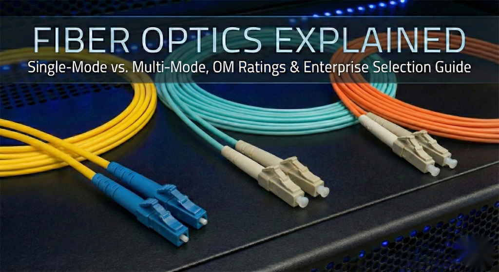
Fiber Optics Explained: Single-Mode vs. Multi-Mode and OM/OS Ratings
Demystifying Fiber Optics: The Backbone of Modern Enterprise Networking
In the world of high-speed networking, fiber optics remain the gold standard for bandwidth, distance, and EMI resistance. While copper reaches its physical limits, fiber continues to evolve, scaling from 1Gbps to 400Gbps and beyond. Understanding the nuances between fiber types is critical for any Cisco Enterprise Architect designing a resilient campus or data center fabric.
Enterprise Use Cases & Fiber Selection
Choosing the right fiber depends heavily on the physical environment and the required throughput. Here are the primary enterprise scenarios:
1. Data Center Leaf-Spine Architecture
Modern data centers utilize Multi-Mode Fiber (MMF) for short-reach connections (up to 100m–400m) between racks due to the lower cost of VCSEL-based optics. OM4 and OM5 are the standards here for 40G and 100G paths.
2. Campus Backbone (Inter-Building)
For connecting separate buildings across a campus, Single-Mode Fiber (SMF) is mandatory. It supports distances of 10km to 40km (and further with specialized optics), making it immune to the distance limitations of MMF.
3. High-EMI Industrial Environments
Unlike copper (Cat6a), fiber optics do not conduct electricity and are immune to electromagnetic interference. This makes fiber the only choice for manufacturing floors with heavy machinery.
Technical Breakdown: SMF vs. MMF
Single-Mode Fiber (OS1/OS2)
SMF has a tiny core (typically 9 microns). It allows only one mode of light to propagate, which eliminates modal dispersion. This is why SMF can carry data for miles without signal degradation.
- Range: Up to 10km (LR), 40km (ER), or 80km (ZR).
- Color Code: Usually Yellow.
- Best for: WAN, MAN, and Campus Backbones.
Multi-Mode Fiber (OM1 – OM5)
MMF has a larger core (50 or 62.5 microns), allowing multiple light rays (modes) to travel simultaneously. While cheaper to implement, it suffers from modal dispersion over long distances.
| Type | Core Size | Max 10Gb Distance | Jacket Color |
|---|---|---|---|
| OM1 | 62.5µm | 33 Meters | Orange |
| OM2 | 50µm | 82 Meters | Orange |
| OM3 | 50µm | 300 Meters | Aqua |
| OM4 | 50µm | 400 Meters | Erika Violet/Aqua |
| OM5 | 50µm | 440 Meters (WBMMF) | Lime Green |
Step-by-Step: Verifying Fiber Interfaces on Cisco Catalyst
Once the physical fiber is in place, you must verify that the SFP (Small Form-factor Pluggable) matches the fiber type and is performing within optical specs.
Step 1: Check SFP Inventory
Use this command to identify if the inserted transceiver is 10G-SR (Short Range/MMF) or 10G-LR (Long Range/SMF).
Switch# show inventory
NAME: "Te1/0/1", DESCR: "10Gbase-SR SFP"
PID: SFP-10G-SR          , VID: V01  , SN: AGM12345678
Step 2: Monitor Optical Power Levels
To troubleshoot “intermittent” fiber links, check the Digital Optical Monitoring (DOM) levels. If the “Rx Power” is too low, the fiber is likely dirty or damaged.
Switch# show interfaces transceiver detail
                                 Optical   Optical
           Temperature  Voltage  Tx Power  Rx Power
Port       (Celsius)    (Volts)  (dBm)     (dBm)
---------  -----------  -------  --------  --------
Te1/0/1 32.5 3.28 -2.5 -5.2Best Practices & Troubleshooting
- Always Clean the Ferrule: 90% of fiber issues are caused by dust. Use a “One-Click” cleaner before every insertion.
- Bend Radius: Never bend fiber cables tighter than a 90-degree angle (roughly the diameter of a soda can) to avoid macro-bends that leak light.
- Match the Type: Never patch SMF into a MMF link (or vice-versa) without a specialized mode-conditioning patch cord.
- Labeling: Always label the OM rating (e.g., OM3 vs OM4) at the patch panel to prevent mismatched speed capabilities.
By understanding these fundamentals, you ensure your Cisco infrastructure is built on a physical layer capable of supporting the next decade of traffic growth.